
파일:Voyager spacecraft structure.jpg
원본 파일 (800 × 1,000 픽셀, 파일 크기: 235 KB, MIME 종류: image/jpeg)
파일 설명

| 설명 |
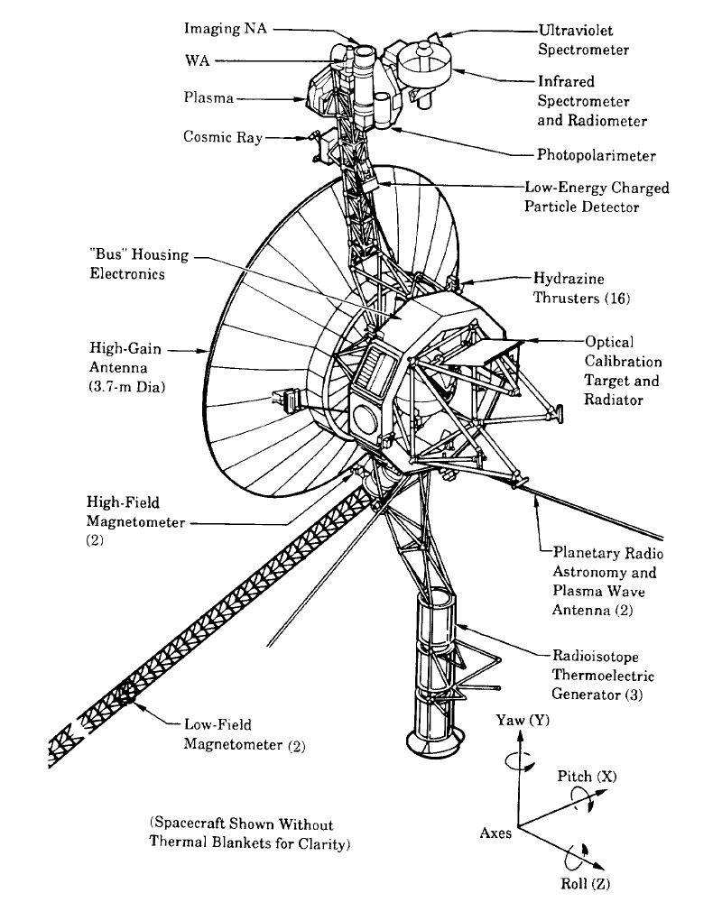
English: The Voyager spacecraft structure - schematic diagram.
The 3.7 metre diameter high-gain antenna (HGA) is attached to the hollow ten-sided polygonal electronics bus, with the spherical tank within containing hydrazine propulsion fuel. The Voyager Golden Record is attached to one of the bus sides. The angled square panel to the right is the optical calibration target and excess heat radiator. The three radioisotope thermoelectric generators (RTGs) are mounted end-to-end on the lower boom. The two planetary radio and plasma wave antenna extend diagonally downwards left and right. The 13 metre long Astromast tri-axial boom extends diagonally downwards left and holds the two low-field magnetometers (MAG); the high-field magnetometers remain close to the HGA. The instrument boom extending upwards holds, from bottom to top: the cosmic ray susbsystem (CRS) left, and Low-Energy Charged Particle (LECP) detector right; the Plasma Spectrometer (PLS) right; and the scan platform that rotates about a vertical axis. The scan platform comprises: the Infrared Interferometer Spectrometer (IRIS) (largest camera at top right); the Ultraviolet Spectrometer (UVS) just above the UVS; the two Imaging Science Subsystem (ISS) vidicon cameras to the left of the UVS; and the Photopolarimeter System (PPS) under the ISS. Suggested for English Wikipedia:alternative text for images: A space probe with squat cylindrical body and a large parabolic radio antenna dish pointing left, a three-element radioisotope thermoelectric generator on a boom extending down, and scientific instruments on a boom extending up. A disk is fixed to the body facing front left. A long tri-axial boom extends down left and two radio antenna extend down left and down right.Polski: Schemat konstrukcji sondy Voyager |
| 날짜 | |
| 출처 | The Voyager Neptune Travel Guide |
| 저자 | NASA |
| 다른 버전 |
이 파일은 다음으로 파생됨: |
라이선스
| 이 파일은 NASA에서 제작하였으므로 퍼블릭 도메인입니다. NASA의 저작권 정책에 따르면 NASA의 자료는 명시하지 않는 이상 저작권의 보호를 받지 않습니다. (Template:PD-USGov, 또는 NASA 저작권 정책 문서, JPL 그림 사용 정책을 참고하세요.) | ||
 |
주의사항:
|
파일 역사
날짜/시간 링크를 클릭하면 해당 시간의 파일을 볼 수 있습니다.
| 날짜/시간 | 섬네일 | 크기 | 사용자 | 설명 | |
|---|---|---|---|---|---|
| 현재 | 2009년 12월 4일 (금) 14:10 | | 800 × 1,000 (235 KB) | Camilo Sanchez | Reverted to version as of 19:07, 24 July 2008 |
| 2009년 12월 4일 (금) 14:07 |  | 744 × 1,052 (1,023 KB) | Camilo Sanchez | Raster to vector version | |
| 2008년 7월 25일 (금) 04:07 |  | 800 × 1,000 (235 KB) | Mirecki | {{Information |Description={{en|1=The Voyager spacecraft structure - schematic diagram}} {{pl|1=Schemat konstrukcji sondy Voyager}} |Source=The Voyager Neptune Travel Guide |Author=NASA |Date=June 1, 1989 |Permission= |other_versions= }} {{ImageUpload|fu |
이 파일을 사용하는 문서
다음 문서 1개가 이 파일을 사용하고 있습니다:
이 파일을 사용하고 있는 모든 위키의 문서 목록
다음 위키에서 이 파일을 사용하고 있습니다:
- bg.wikipedia.org에서 이 파일을 사용하고 있는 문서 목록
- da.wikipedia.org에서 이 파일을 사용하고 있는 문서 목록
- en.wikipedia.org에서 이 파일을 사용하고 있는 문서 목록
- fi.wikipedia.org에서 이 파일을 사용하고 있는 문서 목록
- it.wikipedia.org에서 이 파일을 사용하고 있는 문서 목록
- ja.wikipedia.org에서 이 파일을 사용하고 있는 문서 목록
- nl.wikipedia.org에서 이 파일을 사용하고 있는 문서 목록
- sr.wikipedia.org에서 이 파일을 사용하고 있는 문서 목록
- zh.wikipedia.org에서 이 파일을 사용하고 있는 문서 목록