사용자:Purzo3/무선조종 모형(Radio-controlled model)

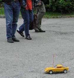
(Saab Sonett II)
무선 조종 모형 (또는 RC 모형)은 라디오 제어를 사용해서 조종 가능한 모형을 말합니다. 자동차, 보트, 비행기,그리고 심지어는 헬리콥터 및 확장 철도차량을 포함한, 모든 유형의 상상가능한 차량에 RC 시스템을 설치해서 만들어졌다.
역사[편집]
무선조종은 1898년에 니콜라테슬라가 시연한 원격 제어 보트에서 시작되었다. 2차 세계 대전을 통해 무선조종 기술은 획기적인 발전을 이룩하였다. 루프트바페(Luftwaffe 독일국방군공군)에서 연합국 함선들을 조준하는데 사용한 조작할 수 있는 날개부착 폭탄입니다. 1930 년대에는 굿브라더스 빌 엔 월트가 진공관 기반으로 제어 장치를 사용한 R/C 취미 사용법을 개척해냅니다. 그들의"Guff(시시한 이야기란 뜻)" 무선 조종 비행기는 국립 항공 우주 박물관도 전시되어 있습니다. Ed 로랜즈는 모형 에어플레인 뉴스에서 새로운 설계를 발표했고, 이는 많은 애호가를 만들어 냅니다. 나중에, 2차 세계대전 이후, 1940 년대 후반부터 1950 년대 중반에 많은 다른 R/C 설계들이 나왔고 어떤것은 상업적으로 판매되었고,버클리의 슈퍼 Aerotrol이 그런 하나의 살예입니다.
원래 간단한'on-off'시스템이 이러한 진화를 사용하여 복잡한 시스템의 릴레이 를 제어하 고무 powered 이스케이프먼트'의 속도와 방향을 알 수 있습니다. 에서 다른 더 정교한 버전으로 개발한 좋은 형제들이라는 TTPW,한 정보를 인코딩하여 다양한 신호의 표시/시간 (펄스에 비례). 상업적인 버전의 이러한 시스템을 신속하게 사용할 수 있게 되었습니다. 의 조정된 리드 시스템을 가져 새로운 세련를 사용하여,금속 갈대를 끌어들여 전송 신호 및 운영의 숫자 중 하나 서로 다른 릴레이가 있습니다. 1960 년대에서의 가용성 트랜지스터-기반으로 장비 led 의 급속한 발전에 완전히 비례적인 서보기반의 "디지털 방식으로 비례적인" 시스템을 달성에 처음으로 개별 구성 요소,다시 구동에 의해 크게 아마추어가 하지만 결과에서 상업적인 제품입니다. 1970 년대에,집적 회로 만든 전자제품은 충분히 저렴한 1960 년대에 설립된 다중-채널 디지털 방식으로 시스템에 비례하여 더욱 널리 사용할 수 있습니다.
By the early 1960s transistors had replaced the tube and electric motors driving control surfaces were more common. The first low cost "proportional" systems did not use servos, but rather employed a bidirectional motor with a proportional pulse train that consisted of two tones, pulse width modulated (TTPW). This system, and another commonly known as "Kicking Duck/Galloping Ghost", was driven with a pulse train that caused the rudder and elevator to "wag" though a small angle (not affecting flight owing to small excursions and high speed), with the average position determined by the proportions of the pulse train. A more sophisticated and unique proportional system was developed by Hershel Toomin of Electrosolids corporation called the Space Control. This benchmark system used two tones, pulse width and rate modulated to drive 4 fully proportional servos, and was manufactured and refined by Zel Ritchie, who ultimately gave the technology to the Dunhams of Orbit in 1964. The system was widely imitated, and others (Sampey, ACL, DeeBee) tried their hand at developing what was then known as analog proportional. But these early analog proportional radios were very expensive, putting them out of the reach for most modelers. Eventually, single-channel gave way to multi channel devices (at significantly higher cost) with various audio tones driving electromagnets affecting tuned resonant reeds for channel selection.
Doug Spreng is credited with developing the first "digital" pulse width feedback servo and along with Don Mathis developed and sold the first digital proportional radio called the "Digicon" followed by Bonner's Digimite, and Hoovers F&M Digital 5.
PWM is most commonly used in radio control equipment today, where transmitter controls change the width (duration) of the pulse for that channel between 920 µs and 2120 µs, 1520 µs being the center (neutral) position. The pulse is repeated in a frame of between 10 and 30 milliseconds in length. Off-the-shelf servos respond directly to servo control pulse trains of this type using integrated decoder circuits, and in response they actuate a rotating arm or lever on the top of the servo. An electric motor and reduction gearbox is used to drive the output arm and a variable component such as a resistor "potentiometer" or tuning capacitor. The variable capacitor or resistor produces an error signal voltage proportional to the output position which is then compared with the position commanded by the input pulse and the motor is driven until a match is obtained. The pulse trains representing the whole set of channels is easily decoded into separate channels at the receiver using very simple circuits such as a Johnson counter. The relative simplicity of this system allows receivers to be small and light, and has been widely used since the early 1970s. Usually a single-chip 4017 decade counter is used inside the receiver to decode the transmitted multiplexed PPM signal to the individual "RC PWM" signals sent to each RC servo.[1][2][3] Often a Signetics NE544 IC or a functionally equivalent chip is used inside the housing of low-cost RC servos as the motor controller—it decodes that servo control pulse train to a position, and drives the motor to that position.[4]
대량 생산[편집]
There are thousands of RC vehicles available. Most are toys suitable for children. What separates toy grade RC from hobby grade RC is the modular characteristic of the standard RC equipment. RC toys generally have simplified circuits, often with the receiver and servos incorporated into one circuit. It's almost impossible to take that particular toy circuit and transplant it into other RCs.
파일:Dc motor and controller.jpg
See also[편집]
- JST connector
- Anderson Powerpole connector
References[편집]
[[분류:모형]] [[분류:무인차량]]
